Muhammed Shehzad Hassan

Materials engineer, M.Sc. RWTH Aachen (Structural Integrity), available now for internships, from March 2027 for permanent roles

Trying to figure out how things break, before they do.

Structural simulation, damage and fracture analysis of composite and metallic parts, with every model checked against theory.

How each project is built

The same four steps in every project, so the result can be defended line by line.

  1. 1

    Theory

    Reduce the problem to a textbook case and state the assumptions.

  2. 2

    Hand calculation

    Predict the key numbers on paper before opening the software.

  3. 3

    Simulation

    Build the FE model, check convergence and boundary conditions.

  4. 4

    Explain the gap

    Compare prediction and result, and account for every difference.

Projects

Deviation bars show the simulation relative to the hand prediction, on a scale of ±10 %.

A 700 bar hydrogen tank: sizing the carbon fibre wall

Tools
Ansys Discovery, Ansys ACP, Ansys Mechanical 2026 R1
Methods
Netting theory, classical laminate theory, layered shells, symmetry modelling, Max Stress / Tsai-Wu / Hashin / Puck
Year
2026

The cylinder of a type 4 hydrogen tank (plastic liner, carbon fibre wall) at 700 bar working pressure. The questions: how thick must the wound wall be, which layer cracks first, and does the tank still meet the burst requirement?

Prediction vs simulation (middle of the tank, 70 MPa)
QuantityHandAnsysDeviation
Radial growth1.15 mm1.153 mm
+0.3 %
Fibre stress, hoop layers950 MPa943.5 MPa
−0.7 %
Fibre stress, helical layers800 MPa800.9 MPa
+0.1 %
Stress across the fibres, innermost layer81 MPa80.8 MPa
−0.3 %
Inverse reserve factor, all criteria2.82.7–3.0Puck mode A: matrix cracking
Inverse reserve factor, fibres only0.430.42–0.46fibre tension
Burst pressure (fibre failure)≥ 157.5 MPa≈ 163 MPameets 2.25 × working pressure
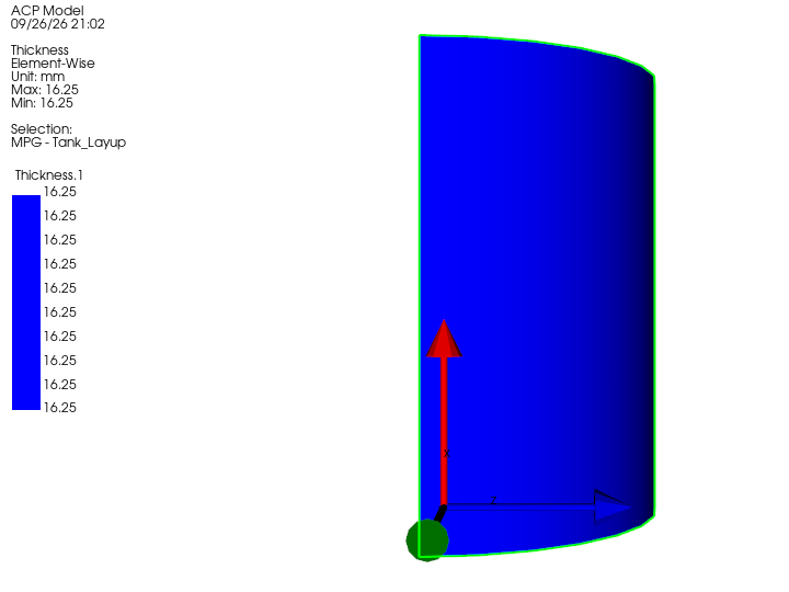
ACP thickness plot of the quarter cylinder, uniform 16.25 mm
Wound wall: 24 helical layers at ±15° plus 41 hoop layers at 90°, 16.25 mm.
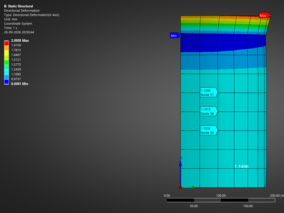
Radial deformation contour with probe values of about 1.15 mm in the middle of the tank
Radial growth 1.15 mm, uniform over the middle; the loaded end at the top is excluded.
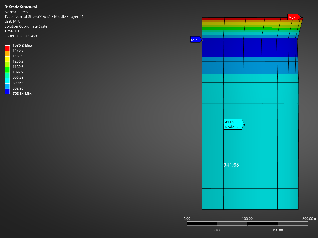
Fibre-direction stress in a hoop layer, 943 MPa in the middle of the tank
Fibre stress in the hoop layers: 943 MPa.
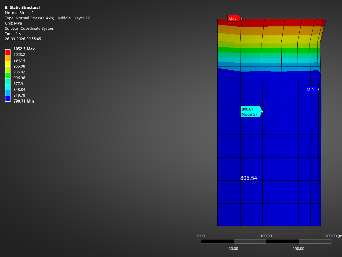
Fibre-direction stress in a helical layer, 801 MPa in the middle of the tank
Fibre stress in the helical layers: 801 MPa.
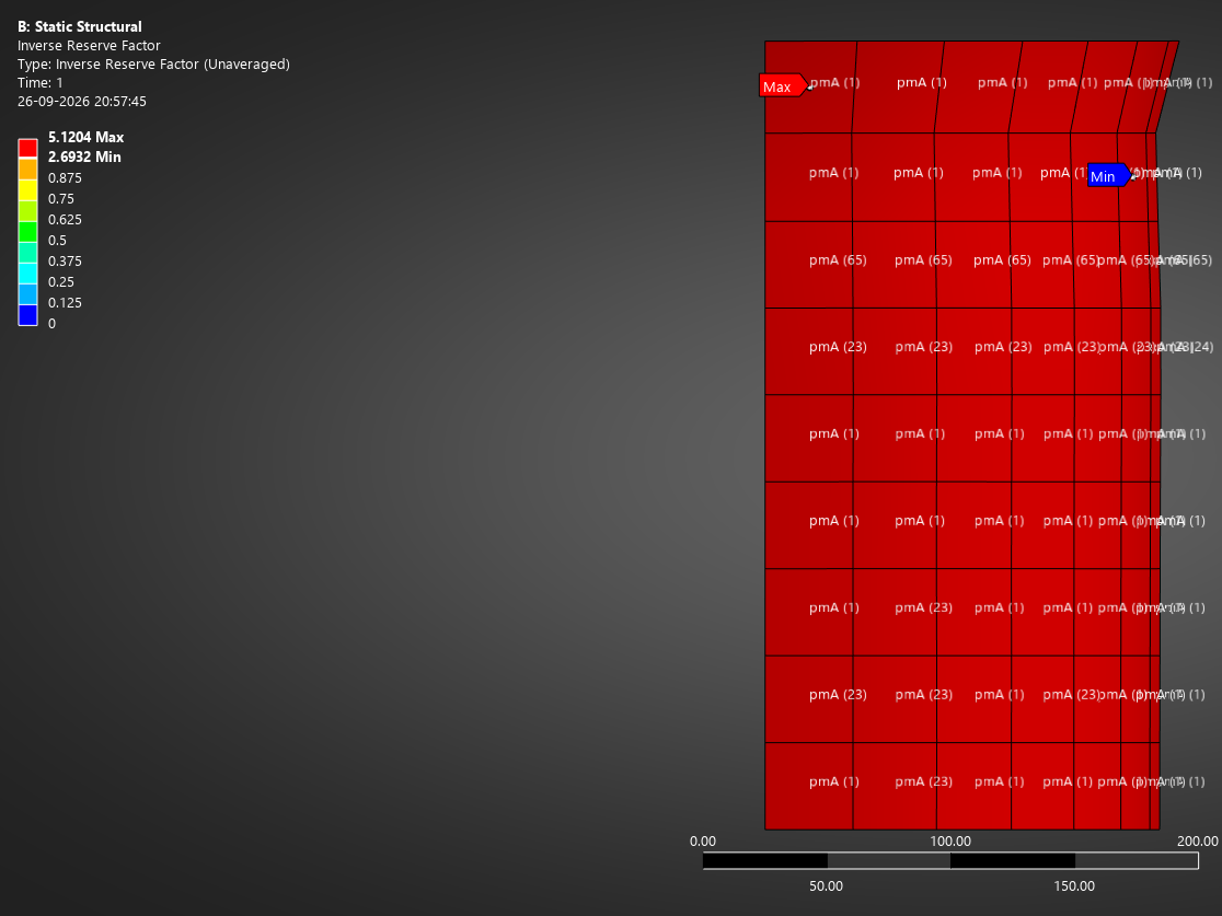
Inverse reserve factor above 1 everywhere, labelled Puck mode A, mostly in layer 1
All criteria: the matrix cracks at working pressure, first in layer 1 next to the liner.
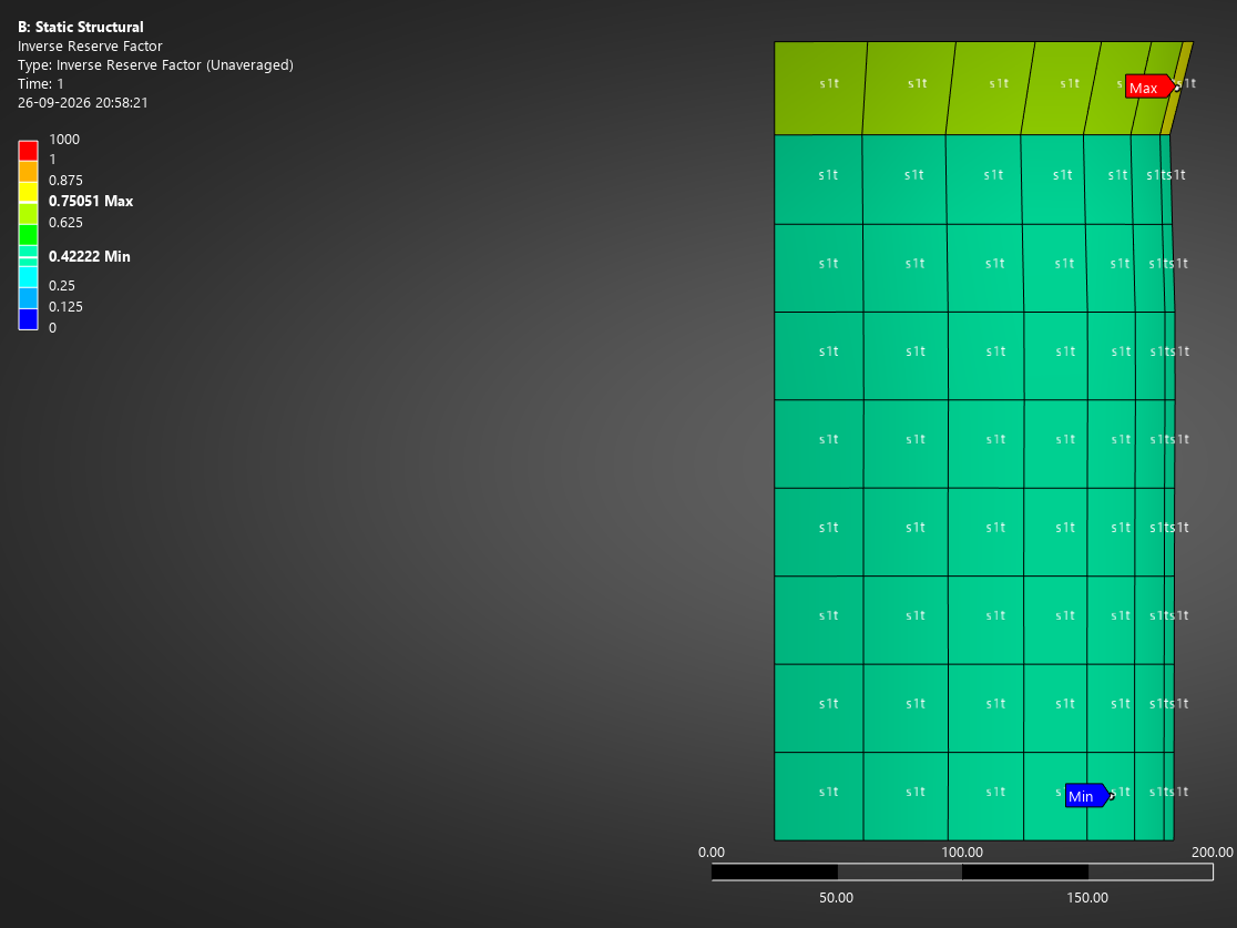
Fibre-only inverse reserve factor between 0.42 and 0.46 in the middle of the tank
Fibres only: 0.42–0.46, so the fibres carry the pressure with margin to burst.
Hand calculation

Wall forces per unit length of a closed cylinder (R = 150 mm), sized at the burst pressure pb = 2.25 × 70 = 157.5 MPa:

Nhoop = pbR = 23,625 N/mm    Naxial = pbR/2 = 11,813 N/mm

Netting theory (fibres carry everything, resin nothing), fibre strength X = 2,231 MPa, helical angle α = 15°:

thelical = Naxial/(X cos²α) = 5.67 mm    thoop = (Nhoop − thelicalX sin²α)/X = 10.21 mm    total = 1.5·pbR/X = 15.9 mm

Rounded up to 0.25 mm plies: 24 helical (6.0 mm) + 41 hoop (10.25 mm) = 16.25 mm. Laminate theory at the working pressure of 70 MPa then gives the strains and ply stresses:

εhoop = 0.0077    εaxial = 0.0063    radial growth = εhoopR = 1.15 mm    σ1: hoop 950 MPa, helical 800 MPa

Stress across the fibres, which decides matrix cracking (strength 29 MPa). A ±15° layer is pulled across its fibres almost in the hoop direction, where the strain is largest:

σ2 = Q22ε2 + Q12ε1: hoop layer 72 MPa (IRF 2.5)    helical layer 81 MPa (IRF 2.8)

Fibre check: 950/2,231 ≈ 0.43, so fibre failure is expected at about 70/0.43 ≈ 163 MPa.

Model and discussion
  • A quarter of the cylinder (R 150 mm, 300 mm long) as layered shells. The 0° reference runs along the axis and the layer normals point outward, so layer 1 sits against the liner.
  • Symmetry built by hand on the three cut edges: on each, the movement through the mirror plane and the two tilts out of it are fixed. The closed dome is replaced by its axial pull, 70 × π × 150² / 4 = 1.24 MN, on the free end.
  • Every result in the middle of the tank agrees with laminate theory within 1 %: the wall works as a membrane there, which is what the hand calculation assumes.
  • Where the model corrected me: my first check looked at the hoop layers (IRF 2.5). Ansys showed that the helical layers crack first. Redoing the hand check for the helical layers gave 81 MPa and IRF 2.8, matching Ansys. The innermost layer is worst because the same growth over a smaller radius means more strain.
  • Error caught by the hand check: the first run gave 64 mm of radial growth instead of 1.15 mm. Checking the edge centroids showed two symmetry supports on swapped edges, which stopped the ring from expanding and forced it to bend. After the fix the result matched the prediction.
  • Near the loaded end the stresses rise: the dome is missing and the end force acts 8 mm off the middle of the wall. The disturbance fades within about √(R·t) ≈ 50 mm, so all values are read in the middle.
  • Engineering meaning: the resin cracks at working pressure while the fibres use only 43 % of their strength. This is why a type 4 tank needs its gas-tight liner, and why the fibres, not the resin, set the burst pressure.
  • Limits: coarse mesh (about 30 mm elements), no dome, linear first-failure estimate of burst. The cylinder–dome junction, a known hotspot in real tanks, is not captured by this model.

The model matched laminate theory within 1 %, and where it disagreed with my first check, the check had looked at the wrong layer.
A cracked aluminium panel: how long until it breaks?

Tools
Ansys Discovery, Ansys Mechanical 2026 R1, Python
Methods
Linear elastic fracture mechanics, J-integral on a pre-meshed crack, symmetry modelling, Paris law fatigue integration
Year
2026

A 100 mm wide, 5 mm thick Al 2024-T3 panel with a 20 mm crack in the middle, loaded from 0 to 100 MPa over and over, like a fuselage skin on every flight. The questions: how hard is the crack tip being pulled open, how long can the crack get before the panel breaks, and how many load cycles does that take?

Prediction vs simulation (crack half length a = 10 mm, 100 MPa)
QuantityHandAnsysDeviation
Stress intensity factor KI18.17 MPa√m18.17 MPa√m
−0.02 %
J-integral4.65 kJ/m²4.647 kJ/m²
−0.11 %
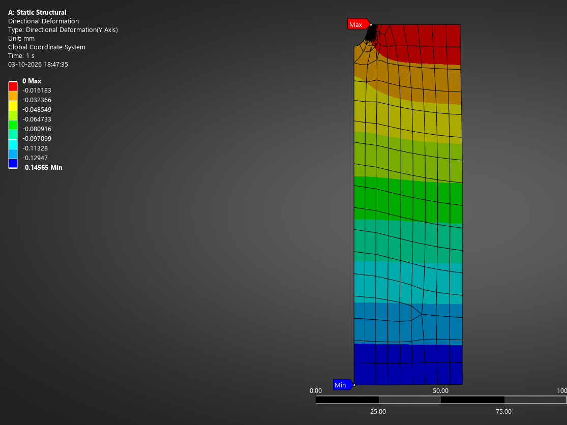
Elongation of the quarter model0.141 mm0.146 mm
+3.4 %
Critical crack half length25.6 mmfracture governs: net-section stress 205 MPa, below the 325 MPa yield strength
Fatigue life, a = 10 → 25.6 mm109,200 cycles109,219 (Python)ignoring the panel width: 134,690 (+23 %)
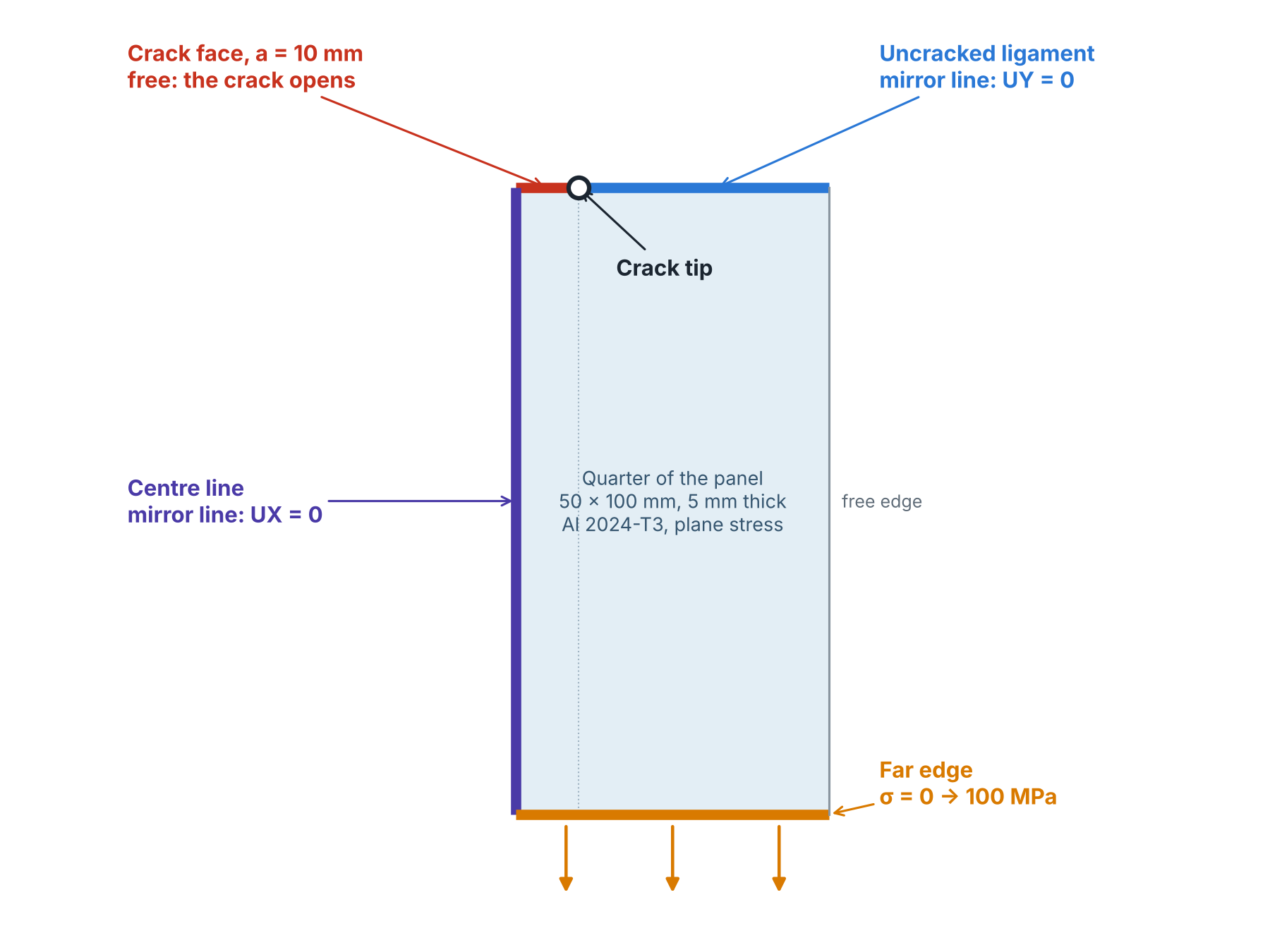
Sketch of the quarter model: left edge held sideways, uncracked part of the top edge held vertically, crack faces free, 100 MPa pulling on the bottom edge
Quarter model: the two mirror edges are held only across the mirror line, and the 10 mm crack face is left free to open.
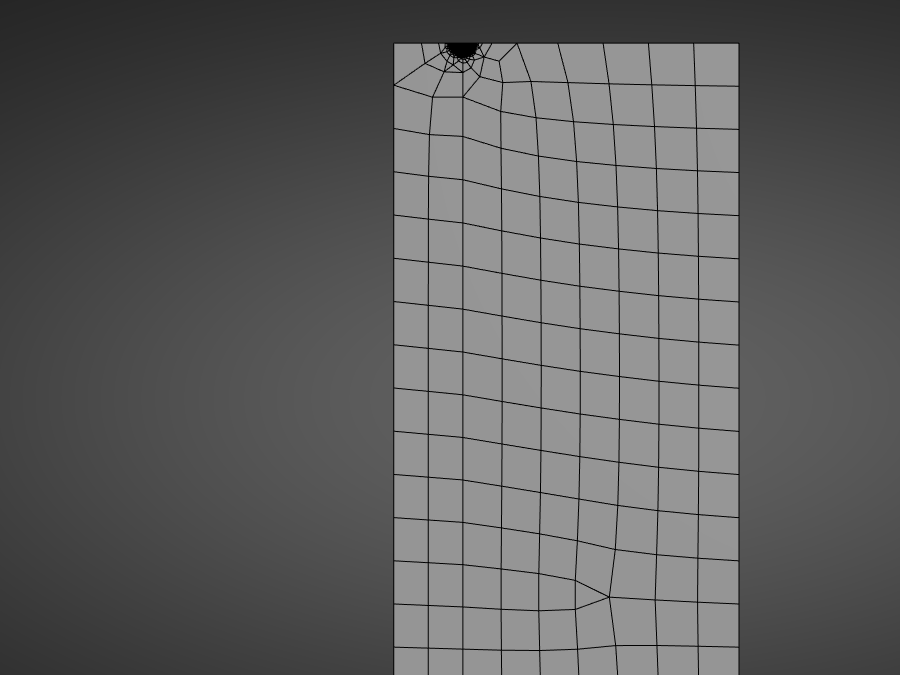
Mesh of the quarter panel, fine at the crack tip in the top left corner and coarse elsewhere
Quarter panel mesh: refined at the crack tip, about 2,700 nodes in total.
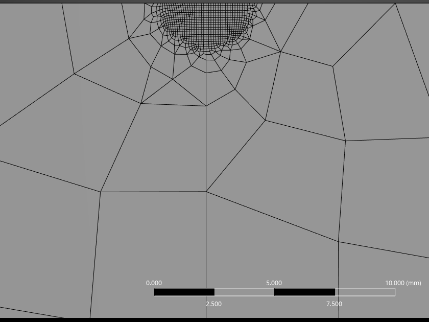
Mesh around the crack tip with 0.1 mm elements in a half circle, growing coarser outwards
0.1 mm elements within 2 mm of the crack tip, coarse elsewhere.
Vertical displacement contour, exaggerated, with the crack face sagging away from the top edge while the uncracked part stays on it
Vertical displacement, exaggerated: the crack face pulls away from the mirror line while the uncracked part stays on it.
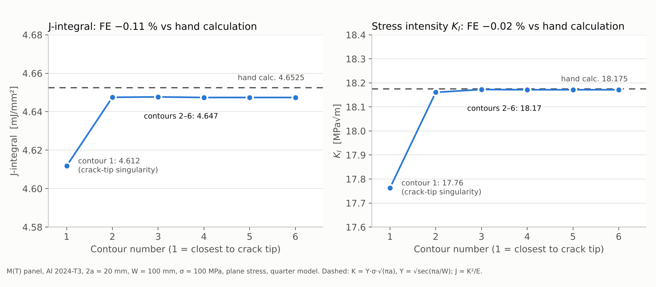
J-integral and K for contours 1 to 6: contour 1 slightly low, contours 2 to 6 equal and within 0.11 percent of the hand calculation
J and K on six rings around the crack tip: the first ring sits in the tip singularity, rings 2 to 6 agree to four digits with each other and within 0.11 % with the hand calculation.
Hand calculation

Stress intensity at the crack tip, with the finite-width correction for a centre crack (W = 100 mm, a = 10 mm):

Y = √sec(πa/W) = 1.025    KI = Yσ√(πa) = 1.025 · 100 · √(π · 0.010) = 18.17 MPa√m

The panel is thin: plane strain would need a thickness of 2.5(KIc/σys)² = 27.4 mm, so plane stress applies and

J = KI²/E = 18.17² / 71,000 = 4.65 kJ/m²

The crack becomes critical when K reaches the fracture toughness KIc = 34 MPa√m. Since Y grows with a, this was solved by bracketing:

Y(ac)·σ·√(πac) = 34 MPa√m    →    ac = 25.6 mm    σnet = σW/(W − 2ac) = 205 MPa < 325 MPa

Fatigue life from the Paris law (C = 10−11, m = 3, Δσ = 100 MPa, R = 0), integrated from 10 to 25.6 mm:

da/dN = C(ΔK)m    Nf = ∫ da / [C(YΔσ√(πa))m]    Y = 1: 134,690    Y(a): 109,200 cycles
Model and discussion
  • A quarter of the panel (50 × 100 mm) in 2D plane stress, 5 mm thick. The left edge may only move up and down, the uncracked part of the crack line may only slide sideways, and the crack face carries no support so the crack can open.
  • The crack is defined as a pre-meshed crack with symmetry on, so Ansys accounts for the mirrored half. J is evaluated on six rings of elements around the tip, with quadratic 0.1 mm elements near the tip.
  • The first ring is 0.8 % low because it runs through the elements at the singular tip. Rings 2 to 6 agree to four digits: J is path independent, which shows the tip mesh is fine enough.
  • The panel stretches 3 % more than an uncracked bar of the same size. The crack makes the panel slightly softer, which the bar formula does not include.
  • Fatigue: the crack grows from 10 to 25.6 mm in about 109,000 cycles. Treating the panel as infinitely wide (Y = 1) predicts 23 % more life, an error on the unsafe side. The Python integration converged from 106,602 cycles with 3 steps to 109,219 with 1,000, the same idea as a mesh study.
  • KIc is a plane-strain value; a thin 5 mm panel is tougher in reality, so the critical crack length is on the safe side.
  • Limits: linear elastic, no plastic zone or crack closure, textbook Paris constants instead of test data for this alloy and stress ratio.

Paper and FE agree on the crack-tip loading within 0.1 %, and ignoring the panel's width would have promised almost a quarter more life than it has.

First ply failure of an open-hole carbon fibre laminate

Tools
Ansys ACP, Ansys Mechanical 2026 R1
Methods
Classical laminate theory, layered shells, Tsai-Wu failure criterion
Year
2026

A quasi-isotropic [0/45/−45/90]s carbon/epoxy plate with a central hole, pulled in tension. The question: where does it start to crack, in which ply, and at what load?

Prediction vs simulation
QuantityHandAnsysDeviation
Laminate stiffness Ex47.0 GPa47.04 GPa
+0.1 %
Far-field strain0.001060.00107
+0.9 %
Peak strain at the hole0.00330.00327
−0.9 %
First ply failure load11.1 kN10.1 kN
−9 %
Failure location90° plies (layers 4 and 5) at the hole edge, predicted and confirmed
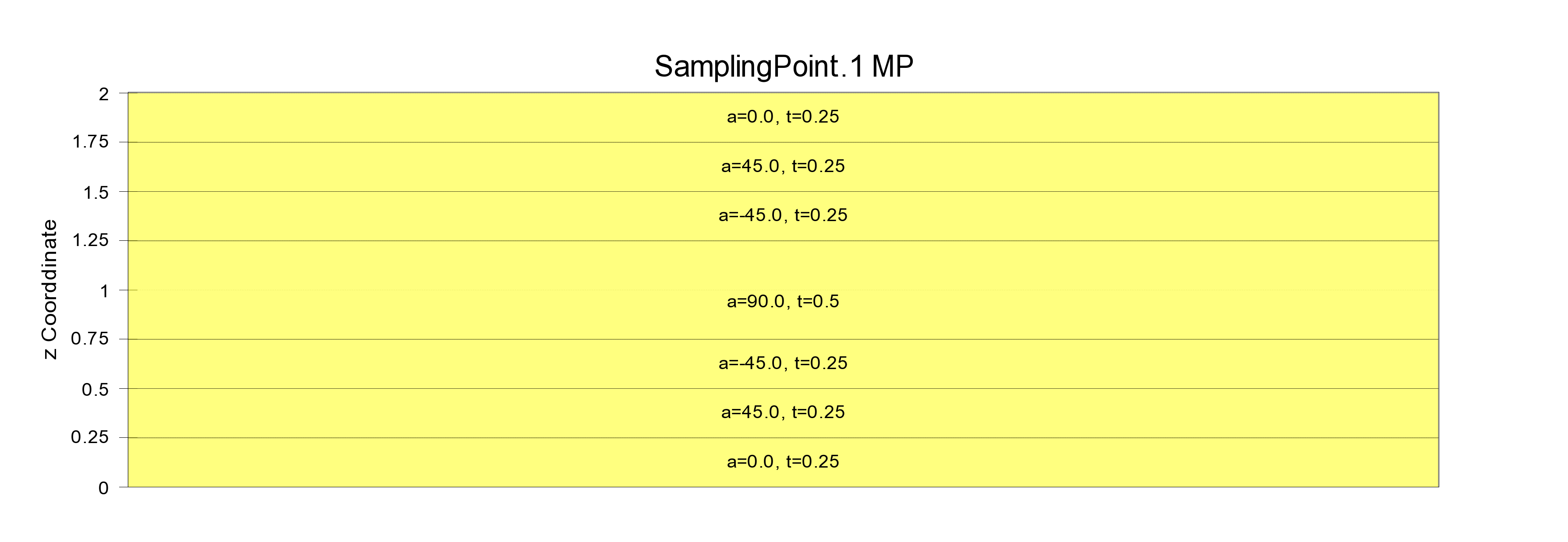
Layup plot showing eight plies of 0.25 mm: 0, 45, −45, 90, 90, −45, 45, 0 degrees
Layup verified at a sampling point: 8 plies, 2.0 mm.
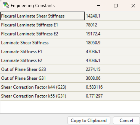
ACP engineering constants window showing laminate stiffness E1 and E2 of 47,036 MPa
Laminate stiffness 47,036 MPa in both directions, matching laminate theory.
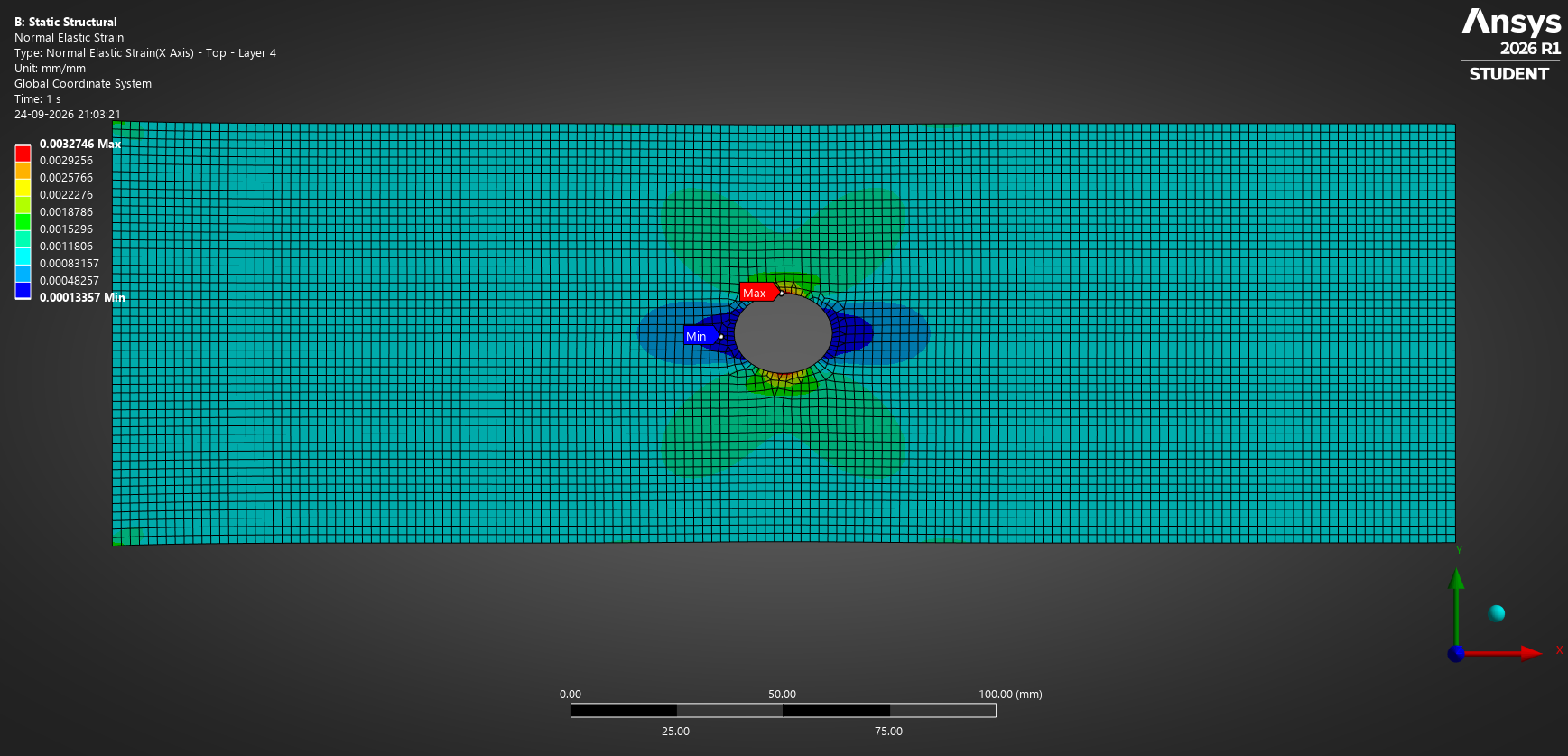
Mid-plane strain contour with diagonal butterfly-shaped lobes around the hole
Mid-plane strain: the lobes follow the ±45° fibres.
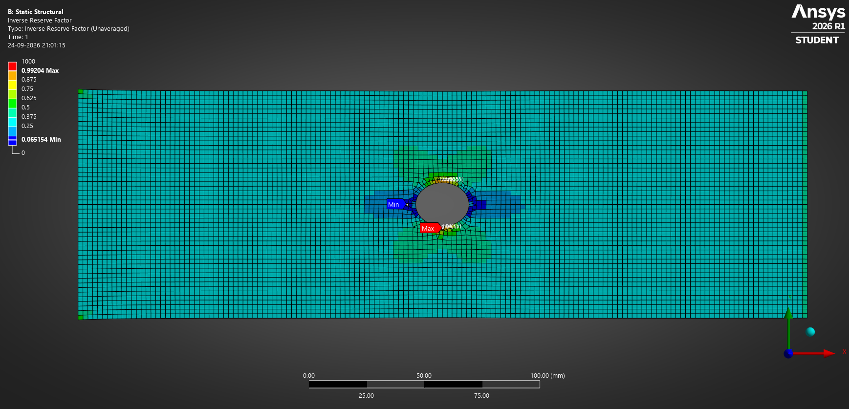
Inverse reserve factor contour with the maximum at the top and bottom edges of the hole
Tsai-Wu inverse reserve factor: 0.99 at 10 kN at the hole edge.
Hand calculation

Ply stiffness from the material data (E1 = 121 GPa, E2 = 8.6 GPa, ν12 = 0.27, G12 = 4.7 GPa):

Q11 = E1/(1 − ν12ν21) = 121.6 GPa    Q22 = 8.65 GPa    Q12 = 2.33 GPa    Q66 = 4.7 GPa

Averaging the rotated ply stiffness over the stack (two plies at 0°, four at ±45°, two at 90°):

A11/h = (2·121.6 + 4·38.4 + 2·8.65)/8 = 51.8 GPa    Ex = (A11² − A12²)/A11 = 47.0 GPa

Peak strain at the hole, then the stress across the fibres in a 90° ply, including the Poisson narrowing:

εx = Kt·σnet/Ex = 0.0033    σ2 = Q22εx + Q12(−νxyεx) ≈ 26 MPa

Against a transverse tensile strength of 29 MPa, the 90° plies are at 90 % of their limit at 10 kN, so first ply failure is predicted at about 11 kN.

Model and discussion
  • Surface geometry meshed with layered shell elements; eight 0.25 mm plies defined in ACP with the 0° direction along the load.
  • Ansys is about 9 % more critical than the hand estimate because Tsai-Wu combines all ply stresses, while the hand check uses only the stress across the fibres.
  • First ply failure is matrix cracking, not rupture: the 0° fibres are at roughly 18 % of their strength at the same load.
  • Error caught by the hand check: the first run showed 88 mm of deflection where 0.33 mm was expected. The plies were stacked on one side of the reference surface, so the load acted 1 mm off-centre and bent the plate. A beam estimate of this bending gave 86 mm, confirming the cause before it was corrected.

A result is only as good as its check: the hand calculation exposed an 88 mm error and traced it to a 1 mm offset.

Stress concentration in a plate with a hole

Tools
Ansys Discovery, Ansys Mechanical 2026 R1
Methods
Linear static FEA, mesh convergence, analytical validation
Year
2026

A 300 × 100 × 5 mm steel plate with a Ø20 mm hole under 25 kN tension, validated against the analytical stress concentration solution.

Prediction vs simulation
QuantityHandAnsysDeviation
Peak stress at the hole157 MPa159 MPa
+1.3 %
Far-field stress50 MPa50.4 MPa
+0.9 %
Elongation0.075 mm0.077 mm
+2.9 %
Mesh convergence of peak stress Peak stress for four meshes: 158.3 MPa at 8,760 nodes, 157.7 at 19,596, 160.7 at 31,915 and 158.7 at 65,605, compared with the analytical 157 MPa. 150 155 160 165 0 20k 40k 60k nodes peak stress (MPa) analytical 157 MPa 4 mm 2 mm 1 mm 0.5 mm
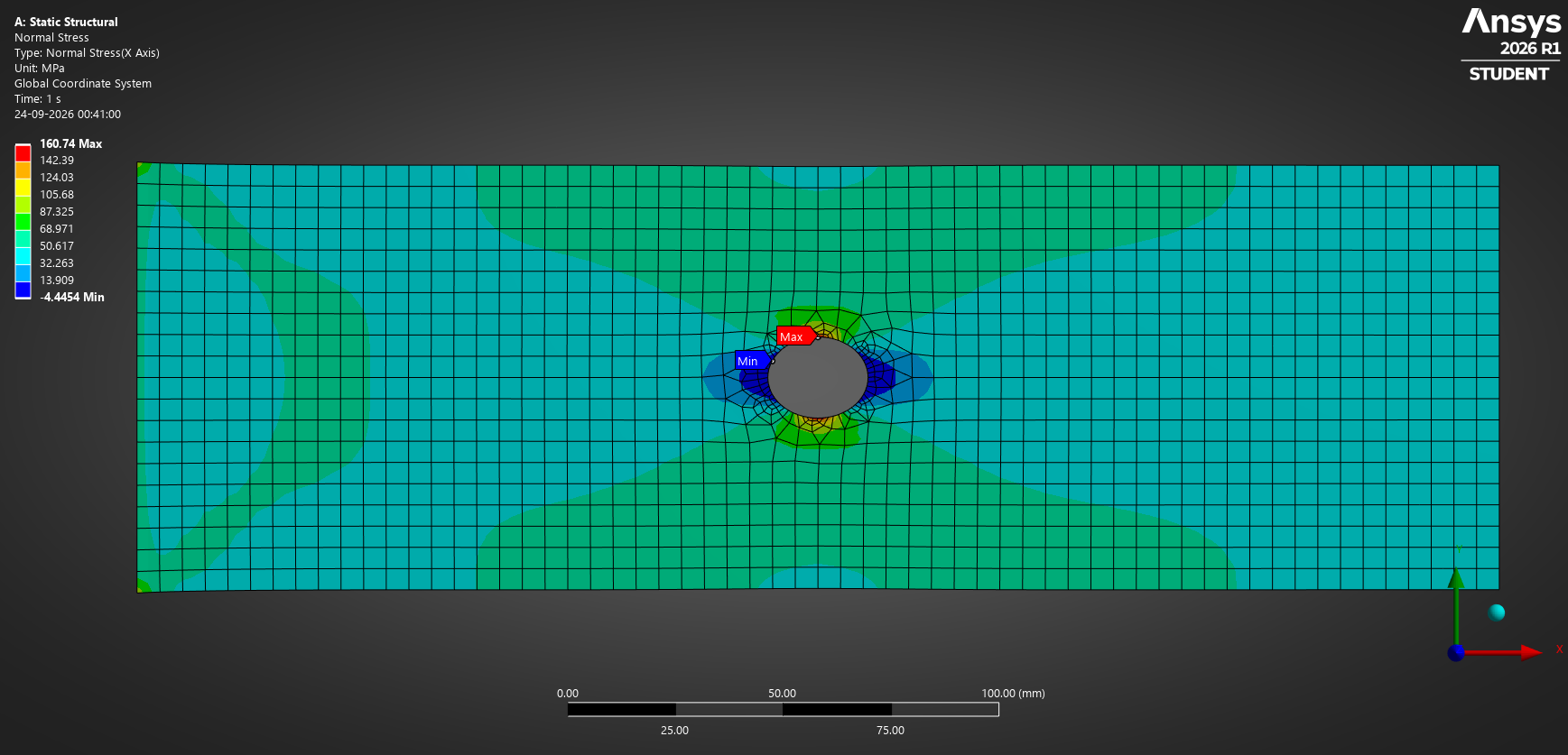
Normal stress contour with the maximum at the top and bottom of the hole
Normal stress along the load: peak at the top and bottom of the hole.
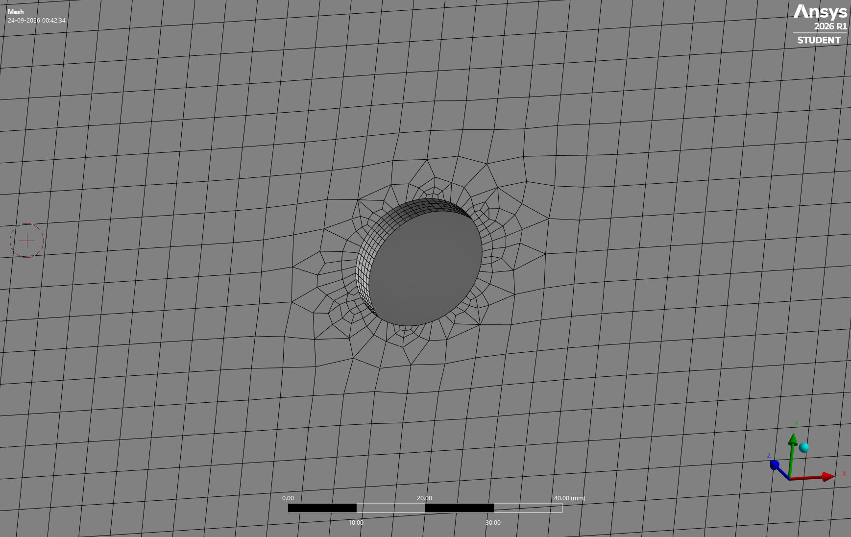
Refined mesh around the hole
Mesh refined locally at the hole, coarse elsewhere.
Hand calculation
σnet = F/((W − d)·t) = 25,000/(80·5) = 62.5 MPa
Kt,net = 2 + (1 − d/W)³ = 2.51    σmax = Kt,net·σnet = 157 MPa
δ = F·L/(A·E) = 25,000·300/(500·200,000) = 0.075 mm
Mesh convergence and discussion
Hole element sizeNodesPeak stressvs 157 MPa
4 mm8,760158.3 MPa+0.8 %
2 mm19,596157.7 MPa+0.4 %
1 mm31,915160.7 MPa+2.4 %
0.5 mm65,605158.7 MPa+1.1 %
  • All meshes fall within ±2.5 % of theory. The small scatter comes from reading the peak at a single node, whose position on the hole edge shifts with each mesh.
  • The 2 mm mesh gives the same accuracy as 0.5 mm with 70 % fewer nodes, so it is the efficient choice for design work.
  • Elongation is 3 % above the bar formula because the hole softens the plate, which the formula ignores.

An FE result is trustworthy once it matches theory and stops changing with the mesh.

Free-surface flow over a bed ridge

Tools
OpenFOAM, FreeCAD, ParaView
Methods
Two-phase CFD, local mesh refinement, validation against flume experiments
Context
University of Oldenburg / Hochschule Emden-Leer, team of three, 2023

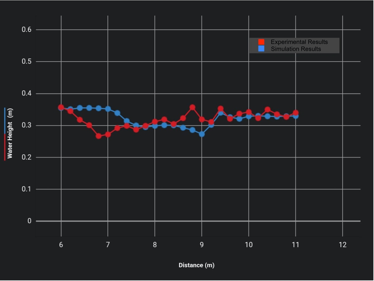
Water flowing over a ridge in a 16 m laboratory flume at 0.152 m³/s, simulated and compared point by point with measured water levels.

Experiment vs simulation
QuantityFlumeOpenFOAMResult
Water level, 26 stations6.0 to 11.0 m downstreammean deviation ≈ 2 cm (7 %)
Agreement downstream of 9.2 mrecovered flowwithin ≈ 1–2 cm
Water-level dipat 7.0 mat 9.0 mshifted downstream
Measured and simulated water levels along the flume
Measured vs simulated water levels along the flume.
Model and discussion
  • Bed ridge modelled in FreeCAD; domain meshed with blockMesh and snappyHexMesh, refined where the lab showed strong turbulence; run in parallel on four cores.
  • Constant inflow of 0.152 m³/s at 0.335 m depth, as in the experiment.
  • The main mismatch is the position of the water-level dip. Likely causes are the coarse base mesh and turbulence modelling near the jump, plus reading errors in a highly turbulent lab flow. No mesh study was done at the time; this is now standard in my work.

Explaining where a model disagrees with an experiment is more useful than a perfect match.

Skills

Simulation
Ansys Mechanical, Ansys ACP, Abaqus (coursework), OpenFOAM
Engineering methods
Laminate theory, stress concentration, damage and fracture mechanics (K, J-integral), fatigue crack growth, failure criteria, analytical validation
Programming and data
Python, C/C++
Background
M.Sc. Materials Engineering, RWTH Aachen; thesis at Fraunhofer IPT on a Digital Shadow for recycled carbon fibre tapes; two years of engineering work in India
Languages
English (C1), German (A1/A2, improving)